Advanced Technologies Powering Modern Water-Cooled Battery Thermal Management Systems
Commercial vehicle water-cooled BTMS represents a convergence of multiple technologies: refrigeration, fluid dynamics, thermal engineering, and vehicle electronics. Understanding these core technologies clarifies system capabilities and informs integration decisions.
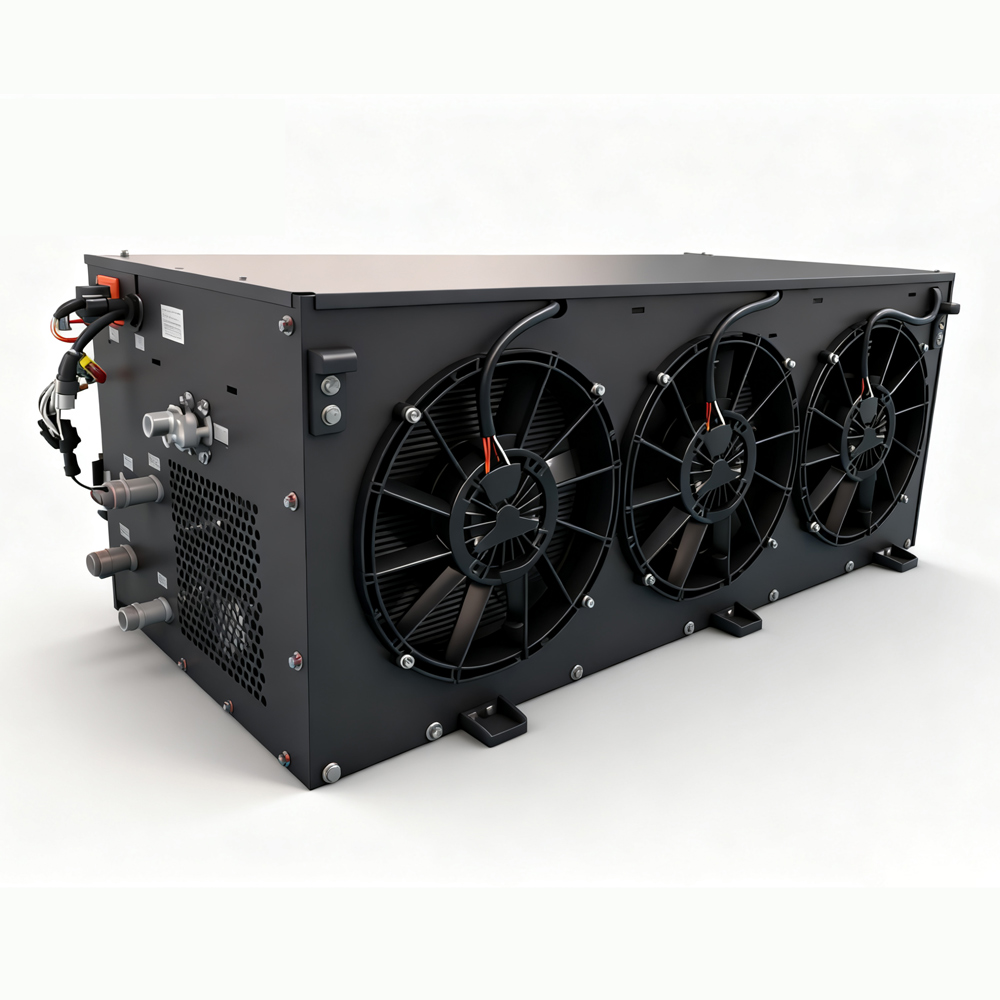
Refrigeration Cycle Technology
The foundation of water-cooled BTMS is the vapor-compression refrigeration cycle. This proven technology efficiently transfers heat from the coolant loop to the ambient environment. Key components include:
The compressor provides the driving force for refrigerant circulation. Scroll compressors offer advantages for vehicle applications: compact size, low vibration, and high efficiency across varying loads. Compressor selection considers refrigerant type, displacement volume, and power consumption.
The condenser rejects heat to ambient air. Condenser design balances heat transfer capacity with packaging constraints. Vehicle-mounted condensers must operate effectively with airflow from vehicle motion and supplemental fan cooling.
The expansion valve precisely controls refrigerant flow into the evaporator. Thermal expansion valves respond to evaporator conditions automatically, maintaining optimal superheat and protecting against compressor damage.
The evaporator absorbs heat from the coolant loop. Plate heat exchangers provide high efficiency in compact packages, ideal for vehicle applications with space limitations.
Coolant Loop Design
The secondary coolant loop circulates between the BTMS unit and the battery pack. Design considerations include:
Fluid selection typically uses 50%/50% ethylene glycol/water solution. This mixture provides freeze protection, corrosion inhibition, and adequate heat transfer properties across the operating temperature range.
Flow rate requirements depend on thermal load and temperature differential. Systems typically require 30-45L/min flow rates to maintain temperature uniformity within battery packs. Insufficient flow causes temperature gradients that stress battery cells.
Pump selection considers both flow capacity and pressure head. Built-in pumps in modern units deliver specified flow rates at operating pressures, eliminating external pump requirements and simplifying installation.
Control System Architecture
Modern BTMS employs sophisticated control systems that manage thermal performance while coordinating with vehicle systems:
Microcontroller-based control algorithms regulate compressor speed, valve positions, and pump operation based on temperature inputs. Proportional-integral-derivative (PID) control provides stable temperature regulation without oscillation.
CAN 2.0 communication interfaces enable integration with vehicle networks. The BTMS can receive commands from vehicle controllers and report status information, enabling coordinated thermal management with other vehicle systems.
Working mode management provides multiple operating states: standby, cooling, heating, and self-circulation. Standby mode minimizes energy consumption when thermal management is not required. Cooling mode activates refrigeration for heat removal. Heating mode engages PTC heaters for cold weather operation. Self-circulation mode operates pumps without active cooling or heating for temperature equalization.
Fault Detection and Diagnostics
Comprehensive fault management ensures reliable operation:
Temperature sensor redundancy provides backup readings and enables sensor validation. If a sensor fails validation, the system can continue operation using redundant sensors while flagging the fault for service.
Self-diagnosis algorithms monitor system parameters for abnormal conditions. High discharge temperatures, insufficient flow, or compressor faults trigger alerts and protective actions.
Real-time power information upload supports remote monitoring and predictive maintenance. Fleet operators can track unit performance, identify trends, and schedule service before failures occur.
Electromagnetic Compatibility
Class III EMC compliance ensures the BTMS does not interfere with vehicle electronics or external systems:
conducted emissions testing verifies noise conducted through power and signal cables remains within limits. Radiated emissions testing confirms the unit does not emit excessive electromagnetic energy.
Immunity testing verifies the BTMS continues operating correctly despite electromagnetic interference from other vehicle systems or external sources.
PCB design incorporates filtering, shielding, and layout techniques to minimize emissions and maximize immunity. Component selection considers EMC performance alongside electrical and thermal characteristics.
Thermal Management Integration
Advanced systems coordinate with vehicle thermal architecture:
Battery thermal management maintains battery temperature within optimal range, typically 15-35°C. This extends battery life, maintains capacity, and enables fast charging.
Powertrain cooling manages heat from motors and controllers, preventing overheating during sustained operation or aggressive driving.
HVAC integration allows shared thermal management resources when appropriate. Some configurations share coolant loops between battery thermal management and cabin conditioning for improved efficiency.
Heat recovery systems capture waste heat for cabin heating, reducing energy consumption in cold climates. This integrated approach maximizes overall system efficiency.